Normal Mapping
To be able to add some extra detail to quads or meshes in our scene, in this engine we decided to add normal mapping, this technique in fact adds an extra layer of realism due to lighting being a very important factor in any engine.
The technique in itself is just a direct interaction with lighting and the normals of a given mesh to emphasize on the depth of a surface so it does not look like a flat surface. In essence this technique basically converts the normals from the mesh into per-fragment (per-pixel) normals, this way we can have little variations on the normals of a mesh and trick the lighting system in the engine to think it has some kind of change in light in specific parts of the mesh otherwise if it was a per-surface it is going to be pretty much the same for each fragment in the screen and it is not going to have any variation, in essence we give the illusion that the mesh is way more complex than it appears without adding any extra geometry.

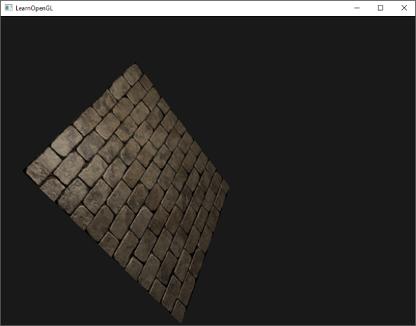
Giving this micro-level details of normals per pixel, we in essence create an illusion where have for example a flat brick plane to look like it is indented where it needs to be like in the following image:
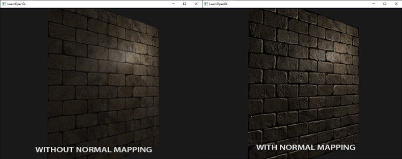
This way we avoid doing an interpolation between surface normals and instead of that we utilize a specific normal per pixel in the screen, the lighting does the rest of the job to create this effect.
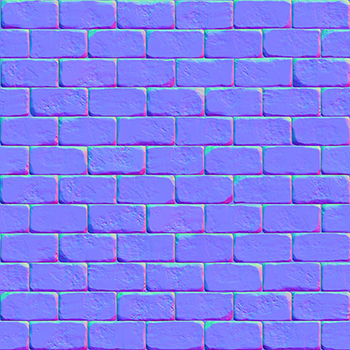
Now, to be able to introduce in the engine we need to follow the usual art pipeline, usually the normals of a geometry are stored in what we know as a normal map, this will hold all the per-fragment information for the normals for given geometry and will allow us to add that realism to the geometry.
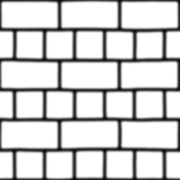
This means that we will be loading a normal texture in the engine through our texture builder and usually a normal map looks very blue-ish in color with reds and greens in between, indicating that the colors correspond to the axis, Blue (0, 0, 1), Red (1, 0, 0) and lastly Top (0, 1, 0) this corresponds to what we see in the texture, greens appear in the top-most part of geometry whereas reds tend to appear in the left-right most parts and in general the faces of the geometry are blue because they are pointing to +Z.
We do not need to forgive that whenever we are processing the texture through the shader we need to normalize in the [0, 1] space instead of the space in which they come [-1, 1] to be able to utilize them correctly. Remember that we can represent the information from a normal texture through the x, y, z coordinates instead of the usual RGB that we do whenever we want to get information from the diffuse.
This means that to be able to normalize the information from the texture in the given limits we do the following shader code:
vec3 transformed_normal = normal * 0.5 + 0.5; // ( This essentially transforms from [-1,1] to [0, 1] )
This allows us to transform from a normal space coordinates to an RGB coordinate space, essentially allowings us to read it without having too much trouble with random normal artifacts. Now, to be able to utilize the normal map we need to sample it and use them for lighting calculations and this is done the following way:
 uniform sampler2D normalMap;

 in vec2 uvs;

 void main()
 {
    normal = texture(normalMap, uvs).rgb
    normal = normalize(normal * 2.0 - 1.0) // We convert them back to range [-1, 1]

    // [......] Proceed with the lighting calculations (Pointlight, Directional, Spotlight)

 }
This all will work perfectly if we have surface sof the geometry or a simple flat plane with normal mapping that is pointing to the +Z direction, in case we rotate it or make it point in any other direction, normal mapping gets ruined, because the normals will still be pointing to the +Z coordinates, think of it as normals being absolute towards the +Z direction no matter how much you rotate the geometry or mesh, this implies that the lighting is going to be done incorrectly and we have officially broken the technique.
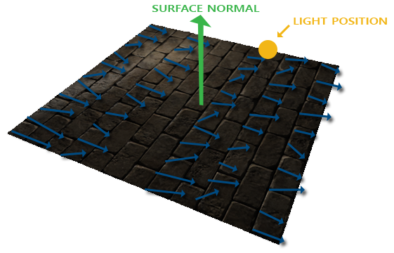
Luckily we have a solution for this, to be able to keep the normals relative to the geometry / mesh we utilize what we call tangent space, this in essence brings the normals to a local space where they are relative to the individual triangles of the geometry, of course always pointing +Z but this time in local coordinates, implying that even if we rotate it, it is going to rotate in the positive Z coordinate taking into account the rotation of the mesh.
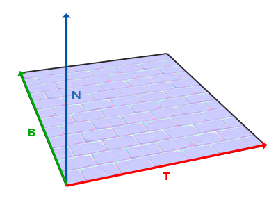
To be able to transform from tangent space to world space and viceversa we need to be able to construct what we call a TBN Matrix to be able to utilize the inverse and the matrix itself to do the transformations of normals comfortably.
As we know, the normals in tangent space point towards the direction of the surface, this leaves us knowing one piece of information, the normal, we are left out with more information that we need to discover, in this case the bitangent and the tangent.
The issue here is that we do not have any other piece of information other than the normal, it is not like we can magically do a cross product and get it done, this means that we will need to do some simple math and it is the following one:
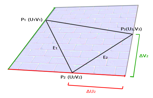
You first need to calculate the edges and delta UV coordinates so you can get the desired vectors, to ease out the mathematics we will do a manual approach so it feels more integral, if we had the following positions, normals and texture coordinates:
  glm::vec3 pos1(-1.0f, 1.0f, 0.0f);
  glm::vec3 pos2(-1.0f, -1.0f, 0.0f);
  glm::vec3 pos3(1.0f, -1.0f, 0.0f);
  glm::vec3 pos4(1.0f, 1.0f, 0.0f);

  // tex coords
  glm::vec2 uv1(0.0f, 1.0f);
  glm::vec2 uv2(0.0f, 0.0f);
  glm::vec2 uv3(1.0f, 0.0f);
  glm::vec2 uv4(1.0f, 1.0f);

 // normal vector +Z
 glm::vec3 nm(0.0f, 0.0f, 1.0f);
We need to calculate the delta UV coordinates which correspond to ΔU2 and ΔV2 which is doing a substraction to the positions:
  glm::vec2 deltaUV1 = uv2 - uv1;
  glm::vec2 deltaUV2 = uv3 - uv1;
You can see that deltaUV1 corresponds to the horizontal ΔU2 delta and the deltaUV2 corresponds to the vertical ΔV2 delta, afterwards the next calculations we will need to do is the edges to be able to calculate the triangle, in this case E1 and E2.
  glm::vec3 edge1 = pos2 - pos1;
  glm::vec3 edge2 = pos3 - pos1;
Once again we can correlate the horizontal and vertical edges with E1 (edge1) and E2 (edge2) respectively, this way we can see that with the edge vectors we essentially have constructed a triangle, having the delta for UVs and the edges of the triangle we can start calculating the vectors we want which in this case are the tangents and bitangents.
float f = 1.0f / (deltaUV1.x * deltaUV2.y - deltaUV2.x * deltaUV1.y);

tangent1.x = f * (deltaUV2.y * edge1.x - deltaUV1.y * edge2.x);
tangent1.y = f * (deltaUV2.y * edge1.y - deltaUV1.y * edge2.y);
tangent1.z = f * (deltaUV2.y * edge1.z - deltaUV1.y * edge2.z);

bitangent1.x = f * (-deltaUV2.x * edge1.x + deltaUV1.x * edge2.x);
bitangent1.y = f * (-deltaUV2.x * edge1.y + deltaUV1.x * edge2.y);
bitangent1.z = f * (-deltaUV2.x * edge1.z + deltaUV1.x * edge2.z);
With this you would already have all the necessary vectors to calculate the TBN matrix.
Note: You need to do the same process for the tangent and bitangent calculation for each triangle in your geometry, usually you would incorporate this piece of code in your object loader in your engine and store them in a vector so you can later build the TBN matrix and pass it to the respective shader.
You have two options here, you can construct the TBN here in the CPU or you can do it in the respective shader, in our case we have it built in the shader itself and you would pass the information through vertex attributes to the vertex shader as following:
layout (location = 0) in vec4 a_position;
layout (location = 1) in vec4 a_normal;
layout (location = 2) in vec4 a_uvs;
layout (location = 3) in vec4 a_tangent;
layout (location = 4) in vec4 a_bitangent;

void main()
{
  vec3 T = normalize(vec3(u_m_matrix * a_tangent));
  vec3 B = normalize(vec3(u_m_matrix * a_bitangent));
  vec3 N = normalize(vec3(u_m_matrix * a_normal));
  mat3 TBN = mat3(T, B, N);
}
Note: We do not need to calculate all the three vectors, with only two of the vectors, one of them being the normals we can do a cross product vec3 B = cross (N, T).
Now after we have the TBN matrix we can take two approaches, either taking the sampled normal from tangent space to world space using the TBN matrix or the opposite, using the inverse of the TBN to transform any vector to tangent space, the rule that we need to abide by is that the calculations need to be in the same coordinate space to avoid any kind of artifacts or weird / unexpected behavior.
In our specific case in Metro Engine we utilize the second option, we bring all the vectors to tangent space to do all the necessary calculations, this means that we first need to inverse the matrix before sending it to the fragment shader.
in mat3 TBN_in;

void main()
{
  mat3 inv_tbn = transpose(TBN_in);

}
Of course, we get the TBN from the vertex shader as input into the fragment shader to later transpose it to be able to transform any vector in the fragment shader to tangent space for the lighting calculations.
Note: The transpose of an orthogonal matrix equals the inverse of it.
And now we need to transform the necessary vectors lighDir and viewDir to tangent space.
in mat3 TBN_in;
in vec2 in_uvs;

void main()
{
  mat3 inv_tbn = transpose(TBN_in);
  vec3 normal = texture(normalMap, in_uvs).rgb;
  normal = normalize(normal * 2.0 - 1.0);

  vec3 lightDir = inv_tbn * normalize(lightPos - fragPos);
  vec3 viewDir = inv_tbn * normalize(viewPos - fragPos);
  // ...
}
And with this, we can calculate all the lighting variables in tangent space given that the normal is in tangent space too, it is a perfect fit for normal mapping to shine and show the technique fully working without caring about the rotation of the geometry/mesh.
We extracted this technique from LearnOpenGL and all the images and mathematics done here are extracted from this website.
Parallax Mapping
As previously mentioned, normal mapping was a technique that added extra realism to a flat surface, using the lighting system we gave the illusion that there is depth. This does not only stop there, we have another technique called “Parallax Mapping” and it is the next step after doing normal mapping, it is specifically related to the displacement mapping family and it is also used to give an illusion or effect that there is a given displacement in a flat surface through height maps.
Usually you would utilize a plane with 1000 vertices and use a height map to tesselate and displace each one of the vertex to add that extra depth and make a geometry even more realistic regardless of the lighting.
We can notice that this can get out of control pretty easily, given that each geometry needs to have around 1000 vertices that will be displaced just to make it look more realistic, it quickly turns out horrendous for performance because it is expected that there is not going to be only that geometry, there are a lot more things running in an engine in a fully fleshed scene, implying that we need to go for an optimized approach to avoid reduction in performance.
That is why this technique is here, instead of using actual geometry vertices to displace and create depth for our geometries, we will be utilizing the texture alongside the height map to create the illusion that there is depth in a flat surface with little to no geometry / vertices like for example a quad that consists of two triangles.
This is what a normal height map would look like:
Now that we have the information about the height at which the geometry shouldbe displaced, we need to alter the texture coordinates of the quad in such a way to make it look like there is depth, of course we need to take into consideration the camera formerly known as the view direction to be able to do the calculations correctly like in the following image:

We calculate the vector V that ends up colliding with the plane in the point A and if we had the height map projected onto the quad, given the specific direction we would be colliding in point B.
Now, you might be thinking, we have the viewDir and the point A from which we get the viewDir, how do we calculate the point B, because we do not have an apparent way to calculate this point B to create an effect of displacement, we should be technically drawing the pixel which corresponds to the vertical of point B.
To be able to calculate this point we need to do a texture coordinate offset it is as simple as offseting the UVs with which we are reading with a small offset that takes into consideration the height map values what we have available to us.
As we have point A we can know the projected value onto the height map which in this case is H(A), after we get that projected point and its length, we can project it onto the viewDir and get an approximation on the desired point B, the following image shows how its done:

Essentially what we are doing is scaling the vector V by the height at the fragment position H(A) so we can get the approximated point H(P) because it is scaled onto the viewDir which is essentially close enough to the point B.
Although this is the rough approximation, it is still very crude and in some edge cases of displacement we might end up overpassing the desired point and project an undesired height and we might end up with artifacts. This next image exemplifies it:

As we can see the projected point H(P) in the texture plane is overpassing the desired height B, proving the point that we can end up with an undesired effect depending on the height map. Another edge case is whenever the plane is rotated, this practically causes the viewDir to not be correct and relative to the forward of the plane to be able to project the height correctly.
Correct Way to do Parallax Mapping
To be able to do this technique correctly and avoiding the previously mentioned edge case of rotation and sometimes the height map doing a weird overpass we need to do two things.
- To be able to fix the overpass that happens depending on the height map, we need to utilize the inverse of the height map, it is in general easier to fake depth than doing it the other way around and the example looks like the following now:

We can see that we still have a point A and desired point B with a direction vector P, this time for us to be able to calculate the texture offset we just substract the vector V in this case it is the viewDir from the camera to the fragment with the point A, this means that the calculations are even simpler because this time we are not obtaining a height value, we are doing it the other way around, we are obtaining depth values and this is done by substracting the sampled heightmap value from 1.0f and on or by simply inverting the texture values in an image-editing software such as GIMP, PHOTOSHOP, etc.
Now to be able to fix the other issue we were talking about, the rotation, we need to be able to convert the viewDir to a local coordinate space that takes into consideration the rotation of the geometry and normals, doesn’t this sound familiar to you ?
(I mean, you essentially read about normal mapping like just a tad bit ago, you should know the answer…)
Yeah, of course! Tangent Space! Correct, we need to also utilize the bitangent and tangent to be able to bring the viewDir to tangent space to be able to do the calculations in the same coordinate space and so they are relative to the given rotation, just like normal mapping but this time without doing any lighting calculations in between!
As far as we can remember, we did pass the TBN Matrix to the fragment shader, so we already have a template from which we can expand and work on parallax mapping to make the geometry look even more realistic and appealing! Given the following fragment shader code we will be doing the following:
in mat3 TBN_in;
in vec2 in_uvs;

// NEW FUNCTION!
vec2 ParallaxMapping(vec2 texCoords, vec3 viewDir)
{
  float height = texture(heightMap, in_uvs).r;
  vec2 p = viewDir.xy / viewDir.z * (height * height_scale);
  return in_uvs - p; // Remember the texture offset we were talking about?
}

void main()
{
  mat3 inv_tbn = transpose(TBN_in);
  vec3 normal = texture(normalMap, in_uvs).rgb;
  normal = normalize(normal * 2.0 - 1.0);

  vec3 lightDir = inv_tbn * normalize(lightPos - fragPos);
  vec3 viewDir = inv_tbn * normalize(viewPos - fragPos);
  // ...
}
Some stuff needs to be explained here in the previous newly added function, we can see that we are clearly sampling from the height map texture that we have previously mentioned, considering that it is the inverted version of the height map. Afterwards we do what we have previosly have talked about, given the tangent space coordinates of the converted viewDir, we take the x and y components and then divide them by its own z component to later scale it by H(A) which from the previous drawings we know is the projected height map onto the displacement map.
Lastly we introduce a new variable called height_scale which essentially servers as a control variable for the parallax effect to tone up/down the height of the effect we are trying to achieve. With a height_scale of 0.1f we achieve an effect like the following for parallax mapping:

As you can observe in the image in the right-most part we have the combined effect of normal mapping + parallax mapping, but you might notice that it is not perfectly placed, we need to trim the edges a bit so it has a perfect quad shape, this often happens because we oversample the texture given the displacement map so we need to constraint it in the [0, 1] range and it is done the following way:
in_uvs = ParallaxMapping(in_uvs, viewDir);
if (in_uvs.x > 1.0 || in_uvs.y > 1.0 || in_uvs.x < 0.0 || in_uvs.y < 0.0)
  discard;
Stepped Parallax Mapping
To be able to do a more precise calculation on the previous parallax mapping technique we can do what we call a steep parallax mapping so we can approach the P value towards the desired point B we already know.
Instead of doing only one calculation of P we take various samples of the same point towards the direction V which is the viewDir towards depth, because remember, we are utilizing an inverted height map and we are now speaking in terms of depth instead of height, essentially you do a “linear interpolation” on the vector P until the sampled depth value is less than the depth value of the current layer, becuase we cut the depth in different depth heights like in the image shown here:

As you can see, the depth is split in interpolations of 0.2 and what we basically do is traverse from top to bottom depth-wise for each layer we compare the sampled depth value to the depth value stored in the depthmap, if it is less than the current depth map value, it means that the layer’s segment of the P vector is not below the surface, this process is continued until you reach a point as previously mentioned where the sampled depth is less than the value of the current layer.
To implement this technique we only have to change a few things in the ParallaxMapping function that we created in our last fragment shader because we have all the information needed, we just need to make the code a bit more complex.
vec2 ParallaxMapping(vec2 texCoords)
{
	//Clculate tangent space coords
	vec3 tangentSpaceCameraPos = transpose(TBN) * u_camerapos.xyz;
	vec3 tangentSpaceFragPos = transpose(TBN) * worldSpacePosition.xyz;
	vec3 viewDir =  normalize(tangentSpaceCameraPos - tangentSpaceFragPos); // In this case we opted to move the calculation of the tangent space view dir inside the function

    const float minLayers = 8.0;
	const float maxLayers = 32.0;
	float numLayers = mix(minLayers, maxLayers, max(dot(vec3(0.0, 0.0, 1.0), viewDir), 0.0));
	// calculate the size of each layer
    float layerDepth = 1.0 / numLayers;
    // depth of current layer
    float currentLayerDepth = 0.0;
    // the amount to shift the texture coordinates per layer (from vector P)
    vec2 P = viewDir.xy * u_parallax_height_multiplier;
    vec2 deltaTexCoords = P / numLayers;

	// get initial values
	vec2  currentTexCoords     = texCoords;
	float currentDepthMapValue = 1 - texture(u_texture_height, currentTexCoords).r;

	while(currentLayerDepth < currentDepthMapValue)
	{
		// shift texture coordinates along direction of P
		currentTexCoords -= deltaTexCoords;
		// get depthmap value at current texture coordinates
		currentDepthMapValue = 1 - texture(u_texture_height, currentTexCoords).r;
		// get depth of next layer
		currentLayerDepth += layerDepth;
	}

	return currentTexCoords;

}
We should get a similar effect to something like this:

Note: Notice how the actual samples of the texture start repeating until they reach the specified goal and then they stop, this gives a false illusion of depth.
This technique is the preferred approach whenever you want to improve the realism of your objects without adding extra geometry and we recommend it, you learn a lot about tangent space and how you can bring vectors to tangent space and world space back and forth to do the necessary calculations, it is a worth the try.
Once again, all the resources and images were taken from LearnOpenGL thanks to this website we were able to explain the technique in an easier manner and hopefully this was helpful!